⇩ Use mouse and click in the interface to jump down to the relevant section for any spesific element ( tabs,buttons or options ) ⇩
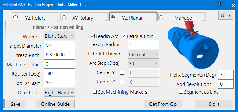
MillBlunt YZ Planar Position (Tab 3):
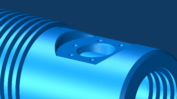
YZ Planar mode are for position milling in the YZ plane. In this tab MillBlunt will calculate geometry that move the tool in Y, Z, and X axis.
Select from the dropdown menu the location for machining.
Blunt Start are in front of a thread and move the tool with the selected pitch in the -X direction.
Blunt End are at the end of a thread and move the tool with the selected pitch in the +X direction.
Its important to select correct location, as this will set the orientation and direction of the 3D geometry in relation if its a Right Hand or Left Hand thread.
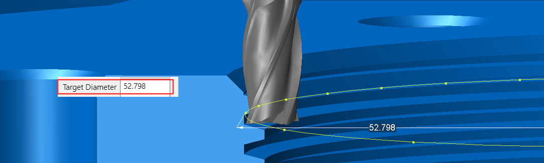
Diameter where the milling tool will start machining at, for removing incomplete threads diameter should be at the root of the external or internal thread.
Pitch of the thread. If the thread uses TPI, the pitch is 25.4/TPI for GibbsCAM in metric and 1/TPI for GibbsCAM in inch.
Pitch = 6.35mm for a 4-TPI thread in metric and Pitch = 0.25 for a 4-TPI thread in inches.
Machine C Start correspond to the same angles as in XY mode, but viewed from top-down :
[0° are centerline in the -Z direction] - [180° are centerline in the +Z direction] - [90° are centerline +Y] - [270° are centerline -Y]
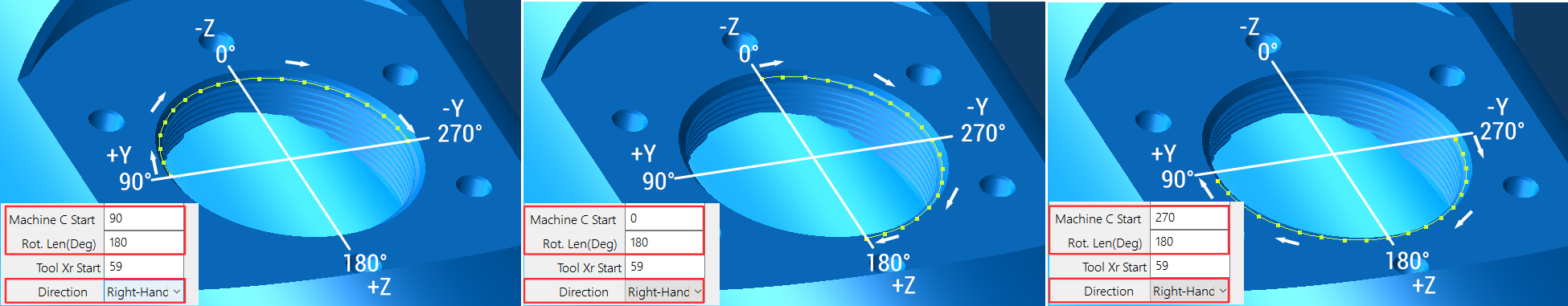
The amount of degrees of the thread to remove, starting incremental from the Machine C Start point. 360 = one revolution, 180 = half revolution.
Any number goes, so 3600 will do 10 revolutions. For most threads atleast 270 degrees will reach full thread form.
Xr position where the milling tool will start. The Xr position are always from the tip of the tool, so its best to use the jog wheel to position the mill and use the X value displayed on the machine display.
Position the milling tool where the tip of the mill overlaps the feathered edge if the thread.

Xr position of milling tool, Blunt Start
Blunt End
Select if its a Right-Hand or Left-Hand thread to mill on.
Select if the lead out should be an arc or line. This defines the shape of the blunt.
Set the Lead Out Line length or Arc Diameter in the corresponding input boxes.
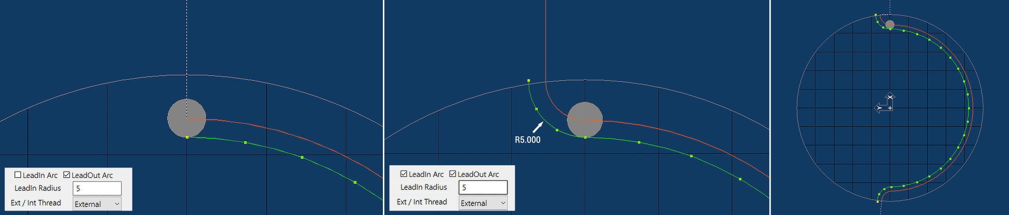
External or Internal thread (Back to top)
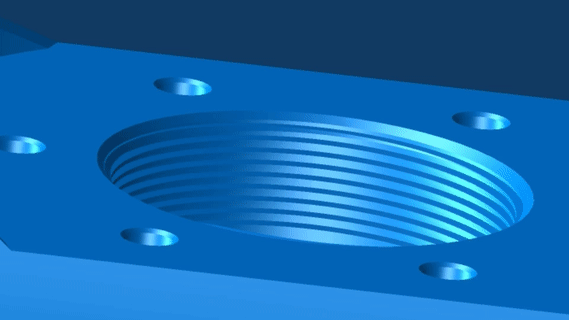
Select if the thread for blunting are External or Internal.
If Lead In / Lead Out Arc are selected, they will be orientated to lead the milling tool in and out of the thread.
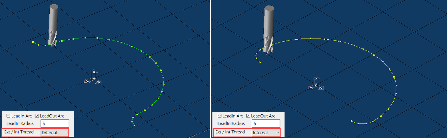
External thread with Lead In & Lead Out
Internal thread with Lead In & Lead Out
If Lead In / Lead Out Arc is used, set degrees between each arc segment in the Lead In Arc. Segments are for one quadrant of a circle with radius set in Lead In Radius.
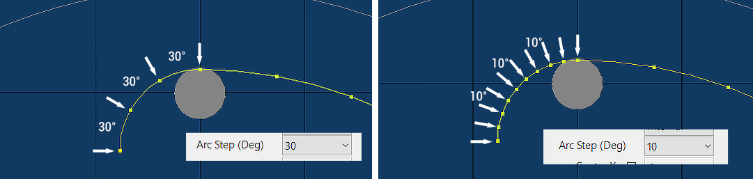
Lead In Arc with 30° Step
Lead In Arc with 10° Step
Use Center Y/Z to place the centerpoint of the geometry in the YZ plane.
Set number of degrees between each arc segment in the helix.
If Segment as Lines is enabled, it will be number of degrees between each line segment.

Helix Segments set to 30°
Add whole revolutions between Lead In and Lead Out. Each revolution follows the set pitch.
This can be used to threadmill a thread.
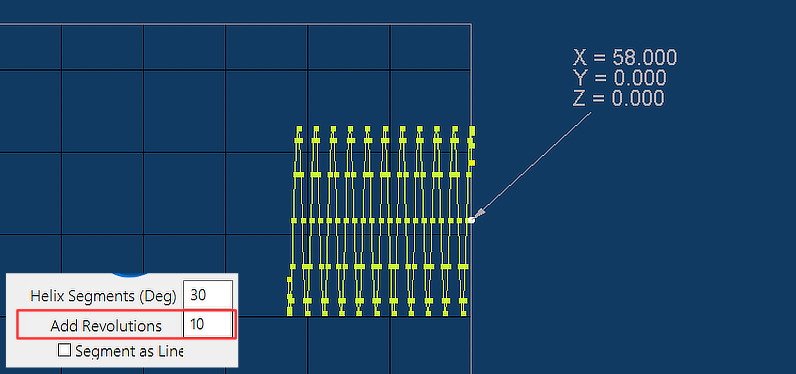
10 whole revolutions between Lead In and Lead Out
Segment as Lines will create the helix with only lines.
When segmenting as lines, set Helix Segments smaller to avoid jagged transitions. The Lead In Lead Out will also be segmented.
Segmenting as Lines can be useful to force a machine to threadmill if there are problems with the ordinary threadmill process.
Some older machine controllers can have problems with running 3 axis simultaneous G2 / G3 and with C axis engaged.
The machine will then run the milling tool with segmented G1 commands and never use G2 or G3 arc commands.

Helix Segments, Arcs 30°
Segmented as Lines 30°
Segmented as Lines 3°
Check this box to automatically select the created geometry and set the machining markers in the correct orientation and side for external or internal machining.
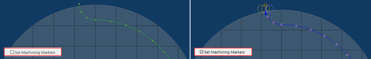
Set Machining Markers - OFF
Set Machining Markers - ON
When redoing geometry from MillBlunt with an existing milling process in the process list, the machining markers will be set correctly on the new geometry.
Then you only need to click Redo on the operation, and it will update the toolpath to the new geometry.
Get From Op ( MillBlunt Contour Op ) (Back to top)
If the selected operation are a previous MillBlunt contour operation, you can read data from the operation and insert everything back into MillBlunt.
When MillBlunt have read data from an existing contour operation, input boxes will be
indicated with green markers.
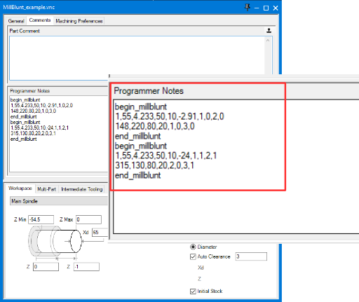
Click 'Save Setup' to store the MillBlunt thread setup into the current open GibbsCAM program.
Any stored data can be imported back into MillBlunt at a later time. All data entries are stored after any existing text here (Programmer notes).
In MillBlunt v2 its not necessary to Save Setups, as all MillBlunt variables are added as a comment to every operation created with MillBlunt, and can be put back with Get From Op button.
After a setup are stored, the button will change state to Update Setup. Pressing Update Setup will update the stored data with the current new one.
All data are stored as lines of text here -> Document Control -> Comments -> Programmer Notes :
Click this button to start the default web browser and open this online documentation directly from the plugin.
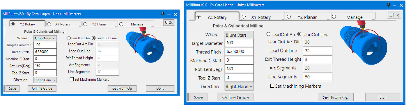
Clicking this button will alternate between normal and large user interface.
 Page accessed : 411 times